|
|
|
 |
|
|
Sb5000 vehicle serial bus analyzer |
|
|
|
- FlexRay, CAN, LIN, UART, I²C, and SPI bus triggers and analysis
- FlexRay eye-diagram analysis
- FlexRay SI Voting Procedures Analysis ** New
- Characterizes electrical characteristics parameters of the FlexRay bus driver
- CAN/FlexRay* bus symbolic triggering, analysis, decoding, and trend display (Supports DBC database for CAN, FIBEX database for FlexRay)
- 4 ch analog + 8-bit logic (SB5310)
- 4 ch analog + 32-bit logic (SB5710)
- Up to 5 GS/s, 1 GHz bandwidth, 6.25 MW (Mpts) memory
- Auto Setup Dedicated to Serial Busses
|
|
| |
| |
 |
|
|
|
|
| |
| |
- Details
- Specification
- Accessories
FlexRay
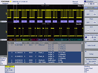
Easy and efficient observation of the physical layer and simultaneous protocol analysis enable you to evaluate the performance of your FlexRay communication system. Evaluation and test through long-duration (multiple-cycle) bus observation answer questions such as whether specific frames are being transferred as designed, whether there are any "glitches" in signals, or whether any data corruption is occurring. The FlexRay FIBEX symbolic triggers, analysis and trend display functions* allow you to activate trigger and display the analysis results by physical values (Message and Signal) in conformity to FIBEX database.
* Compatible with the FIBEX version 2.0
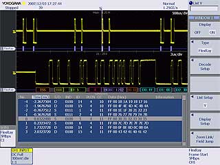
In addition to Frame Start, ID, Cycle Count, Data, and other conditions, the SB5710/SB5310 serial bus analyzer allows you to trigger on CRC, BSS, and FES errors to capture physical layer voltage waveforms. The protocol analysis results list and decode displays are shown simultaneously with the waveform display which is updated in real time on every trigger (Figure 1). If a communication abnormality occurs, this helps you to identify causes including whether the problem is hardware or software related.
The analysis results list can be saved to a text file in csv format. You can make a "Field Jump" in the zoom screen to the top of a specific field in a specific frame (the CRC field, for example), or search the entire range of captured data for the field's waveform by specifying field and frame conditions. |

Figure.1: FlexRay waveform, list, decode display example

|
|
| Measurement Items |
|Z|, |Y|, Q, Rp, Rs(ESR), G, X, B, Θ, Ls, Lp, Cs, Cp, D(tan δ) |
| Measurement ranges |
| |
1kΩ range |
10kΩ range |
100kΩ range |
| Z, R |
100mΩ to 2kΩ |
1kΩ to 20kΩ |
10kΩ to300kΩ |
| C |
0.66pF to 15.9µF |
0.066pF to 1.59nF |
4.4fF to 159pF |
| L |
0.133nH to 3.18mH |
1.33µH to 31.8mH |
13.3µH to 477mH |
| Θ |
-180.00° to 180.00° |
|
| Measurement Frequency |
100 kHz to 120 MHz ( 100Hz to 100kHz steps ) |
| Basic accuracy |
|Z|: ±0.5 % rdg. , phase angle: ±0.3° |
| Output Impedance |
50 ±10 ohm (at 100 kHz) |
| Measurement Signal Level |
5 mV to 1 V, 20 mA max. ( up to 10.00 MHz )
5 mV to 500 mV, 10 mA max. ( above 10.01 MHz )
Setting Resolution: 1mV steps
200 µA to 20 mA: 1 V max. ( up to 10.00 MHz )
200 µA to 10 mA: 0.5 V max. (above 10.01 MHz)
Setting Resolution: 10 µA steps |
| Measurement Time |
6 ± 1 ms (nominal) |
| Other function |
Monitor Function, Limit Function, Average Trigger Function, Load Compensation Function, Key Lock Function, Comparator, Classification ( BIN ) Measurement, Correlation, Compensation Function, Panel Save and Load, Measurement Value Storage, Zoom Display Function, Continuous Measurements, Audible Beeper, Numerical Display, Digit Setting Function, Display Setting Functions, Printer Function |
| Interfaces |
GP-IB, RS-232C and EXT I/O ( standard ) |
| Power |
100 to 240 VAC, 50/60 Hz, 50 VA |
| Dimensions and Mass |
Approx. 360W×130H×360D mm, 8.3 kg |
| Supplied accessories |
Power cord |
|
|
No Accessories for this product
|
|
|